The Tank is Wired
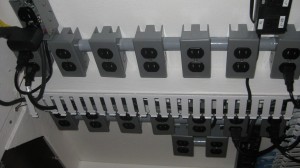
There are two 20A isolated circuits to power the tank, with GFCI breakers installed in the panel. There are 28 individual power receptacles.
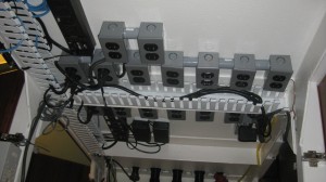 I will be using a Digital Aquatics Reefkeeper Elite to control some functions, so there are 2 PC-4 power units to provide eight controllable outlets. Cables will be managed by PVC wiring trough.
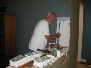
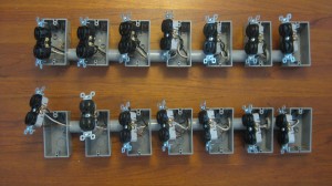 This shows assembly of the outlets, boxes and associated wiring.
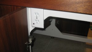
This is a power outlet to make it convenient to plug in a pump, light or tool. The lower outlet is controlled by a relay that is wired to the water makeup float switch. This makes a safe and handy way to pump water into the tank when doing a water change.
All of the controllers, power transformers, etc. are attached to the stand with 2″white velcro tape. It allows easy maintenance access and flexible mounting arrangements.
The Tank Has Water in it!
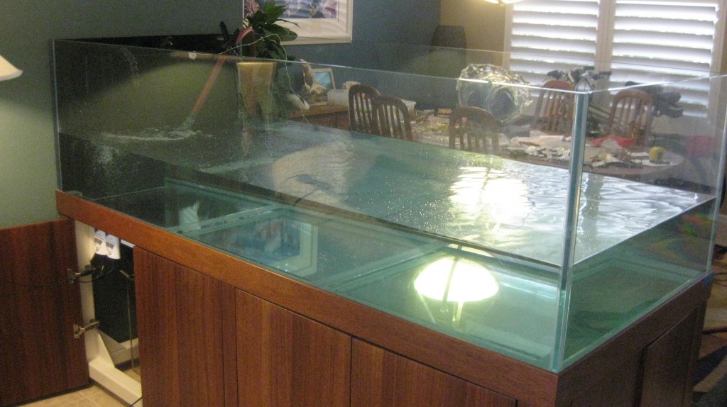
The system is finally ready for a fresh water fill. Kind of a hold your breath moment, but all went well. I am very pleased with the overflow system. It is absolutely silent and there are no air bubbles entering the sump at all. This will not only eliminate noise, but stop the salt creep that is typical of sump areas. The VorTech pumps are very quiet, and are moving a lot of water.
Vortech Pumps
Vortech MP-60 pumps are installed on the back wall of the tank.
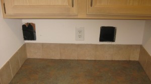 There is a pantry on the opposite side of the wall that allows me to install the dry side of the VorTechs through the wall.
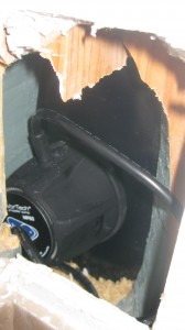
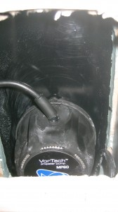 Both pumps are accessable from the other side of the wall. This also isolates much of the noise these pumps are known for.
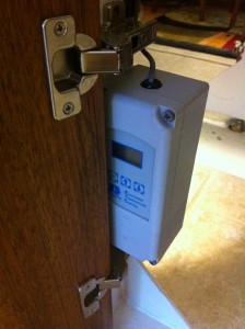
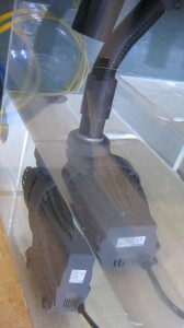
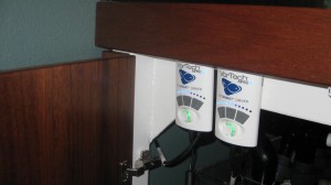 The VorTech controllers are attached behind the cabinet door with velcro.
Drains Installed
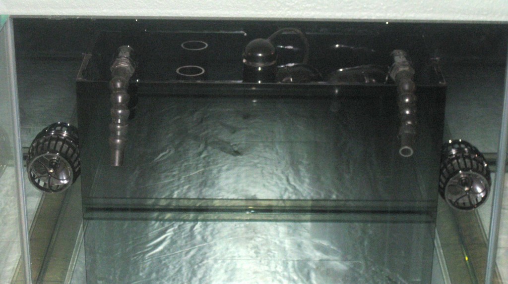
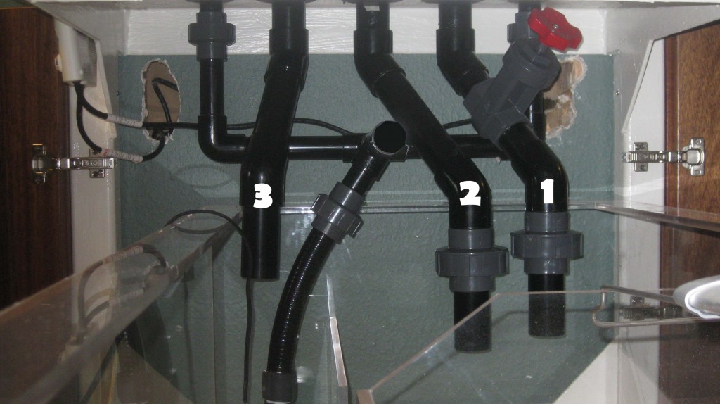 The 3 drains are 1 1/2″ black PVC and the 2 returns are 1″ black PVC. The drain method used is known as the “Bean Animal”, named after the forum handle of the reefer that perfected the design. It consists of three drains, the one on the right (1) with a gate valve is a full siphon, meaning that is is adjusted to a point where no air is being drawn in with the water. The center drain (2), or clear channel has a small air vent installed on the top of the standpipe above it, allowing a small amount of excess water to drain without drawing much air into the water stream. The left drain (3) is an emergency overflow. It is installed so that it will handle all the water if necessary because of a blockage on the other two drains.
The left emergency overflow is open on the top while the other two look very much like a typical durso, except that the full siphon on the right has no air hole.
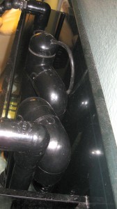 The airline tubing is fastened just above the water level so that if the water rises in the overflow box it will draw water and become a full siphon which handles much more volume. I will update this post later with some photos of the standpipes out of the tank.
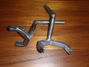
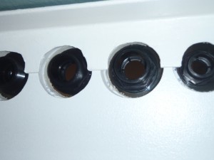 Installing the bulkheads presented a challenge when it came to tightening the bulkhead nuts. With 1 1/2″ of foam and plywood between the tank bottom and the 1/4″ steel of the stand, it became impossible to tighten the nuts with regular tools.
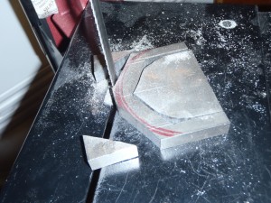 I used a bandsaw to rough cut the jaws of a wrench.
After some filing and a little bit of help from Iggy and his welder, I now have two wrenches that will allow me to tighten or adjust the bulkhead nuts.
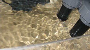
With the pump running, there are no bubbles being released into the sump. No air also means no noise.
The return pump is a Water Blaster HY-7000 by Reef Octopus. It is rated 88 watts 97% efficiency Max Flow=1800gph Max Head=12ft. Very quiet.
Stand Completed
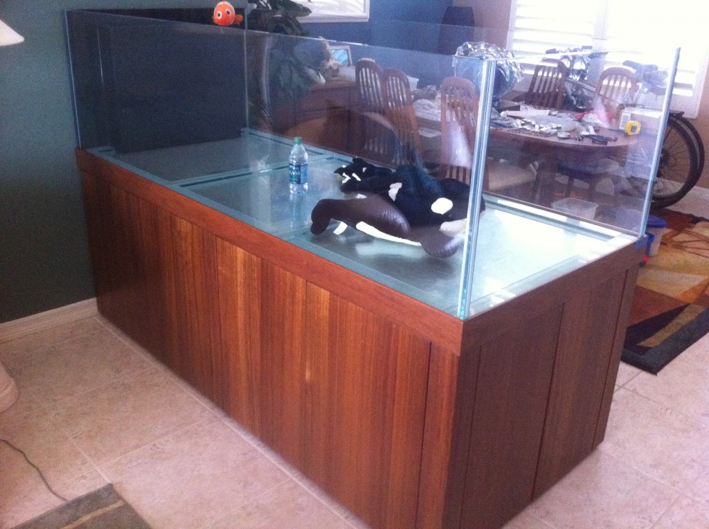 At last, the stand and woodworking is complete. I had a lot of people ask when there would be water in the tank, and as you can see there is indeed water in the tank.
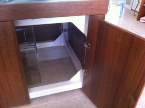 The hinges are mounted to the stand with #8 stainless steel machine thread screws. They are spring closing hinges that act when the door is about 6″ open. They work nicely with standard magnetic latches without using the striker plate. The hinges also allow the door to be completely removed. Drilling and tapping 40 holes in 3/16″ steel was tedious.The hinges were given a coat of clear acrylic spray to help protect them from the salt environment.
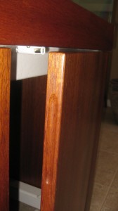 Here is a view of the cabinet door edges. A groove was cut with the shaper on the edge to allow your fingertips to grip the door when it is against the magnetic catch.
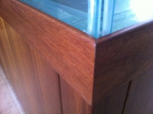 The trim was attached with liquid nail adhesive. A bead of silicone was added on the top side to seal any water drips from the glass.
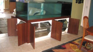
All of the doors can be opened for service. They also have removable hinges so the doors may be taken off.
Building the Cabinet Doors
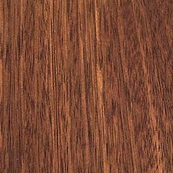
The Angélique hardwood was supplied by Amazon Exotic Hardwoods, owned by fellow reefer James Lie. James has a tank of similar size for which he built a stand using Zebrawood.
The lumber is 10′ lengths of 6″ x 1″
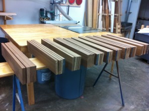 A long time friend from my sailing buddies, Kenny Eads is a master cabinet builder and has a shop in Casselberry. He is my Jedi Master of woodworking, and allowing me to use his shop to build the cabinetry.
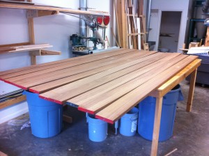
Here we have the boards cut to the cabinet door height.
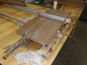 Each cabinet door will have four boards glued together. Because the planer will not handle the width of the full door, I am gluing two boards which will be planed, then glued to the other half.
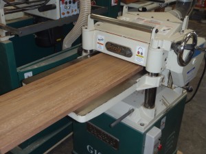 The two boards are now planed to a smooth surface.
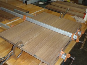 Two sets are glued together for the full cabinet door width.
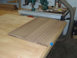 The door is now cut square with the side with a sliding jig on the table saw to make the corner a perfect 90° angle
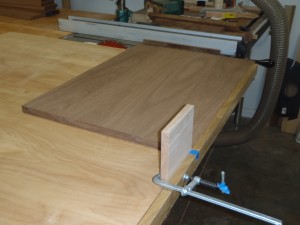 The door is flipped over and trimmed to the exact width set by a stop block.
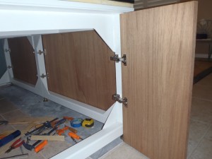 Hinges were mounted to the doors, then the hinge attachments ere made to the stand. Drilling and tapping 56 holes in 3/16″ and 1/4″ steel was quite tedious.
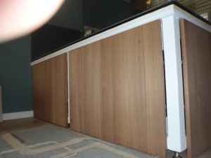 The stand looks much more finished with all the doors mounted. The corners and styles are not yet fitted.
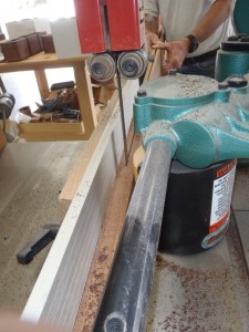 Here we are sawing a board to be used for the trim between the tank and doors. We are using a bandsaw with a power feeder to yield two 3/8″ boards from one plank.
Parts
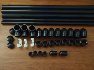
I ordered some 1″ and 1 1/2″ black PVC Plumbing parts for drains and returns.
I picked up the hardwood for the stand from James Lie at Amazon Exotic Hardwoods. The wood is Angelique, a South American import wood. It will take about 60 board feet to make the cabinet doors. I will be building the stand the week after Thanksgiving with the help of a cabinet builder and friend, Kenny Eads.
The TANK MOVE
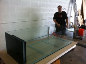
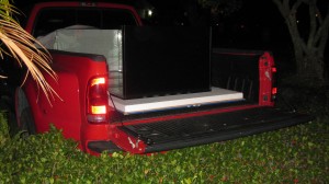
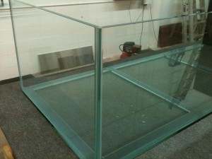
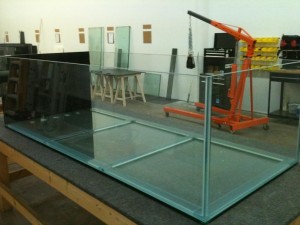
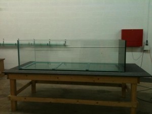
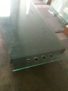
The tank has been completed and waiting at Reef Savvy for a number of months now, and the stand is finally ready. Chad Newman offered to take a day off and drive me down to Miami, and Al Schreiber came along for the ride. It was a good thing we had the help loading the tank at the Miami end. We had one end of the tank on a lift and it took everything all four of us could do to raise one end of the tank level with the pickup bed.
This 7 foot monster weighs 700 lbs. (The tank, not Felix)
We backed up to the front door at home, which shortened the distance for the carry significantly. We used a sheet of plywood and a sheet of 2″ foam to cushion the ride. Chad’s big duelie truck was the perfect ride for the trip (except for the amount of diesel we burned).
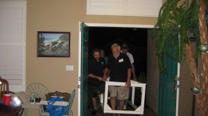
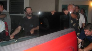 Here is the start of the lift. We have eight big boys here, and we needed every one of them!
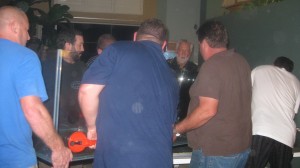 Here we are almost in place. Watch the fingers!
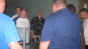 What a relief to see the tank in its final resting place.
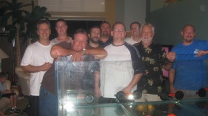
A real big thanks to the moving crew- Al Schreiber, Michael Harnett, James Goodyear, Iggy Galarza, Chad Newman, Ed Newman, David Hill, Rick Loewen (me), and Skippy Dooling.
The Stand Completed
SITE PREP
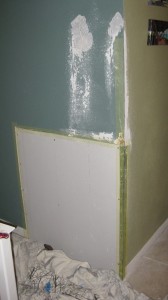
There was some drywall work to be done before the stand was placed. Not shown are some holes in the wall to accommodate a pair of Vortec MP-60s. There will be holes in the back side of the wall in a pantry area to allow access to the Vortecs.
PAINT
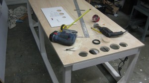 The stand was brush painted with Sherwin Williams MacroPoxy 2-part epoxy paint. It was very thick and difficult to apply smoothly. It took two coats to cover the bare metal. Next, a piece of 3/4″ plywood was cut to size and holes drilled for the 1 1/2″ drains and 1″ returns.
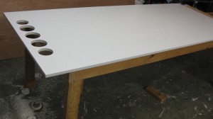 The wood was then coated with a coat of epoxy for waterproofing.
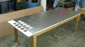 A piece of 3/4″ foam insulation was cut, similar to the plywood. This will be placed directly under the tank to provide a surface that will conform to irregularities.
MOVING THE STAND
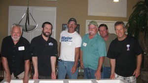 I recruited a group of friends to help move the stand after a nearby ORCA club meeting. Pictured are Rick Loewen (me), Iggy Galarza, Mike Martin, Terry Alexander, James Goodyear and Al Schriber. The stand weights about 350 lbs., It easily took all of us to move the stand.
In the front door we come.
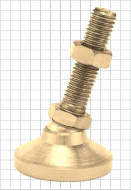
 The stand is now in place. Note the leveling feet. They are industrial leveling feet with 1/2″ thread and a 2″ swivel pad.
Back from the Sandblaster
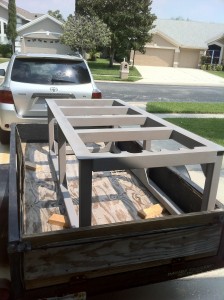
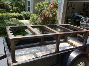
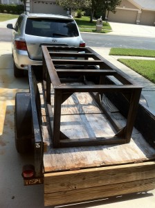
Just got the tank stand back from the sandblaster. Nice and clean, ready to paint. It is very critical to keep it dry after they blast it with aluminum oxide to remove all of the scale and rust. Even the slightest amount of moisture will start it rusting. It was the perfect day to do the job with the humidity only at 35%, very unusual for Florida.
Back from the Welder
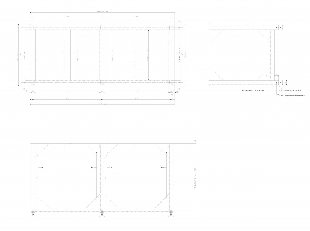
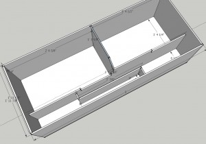
Stand Design
The Stand
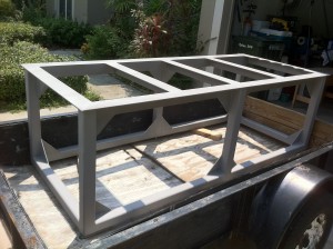
The stand construction is finally underway! The design phase took a while, but we are in the fabrication phase now. I want to thank Robert Wright, a fellow reefer and steel fabrication engineer in south Florida for some incredible advice and design work on the stand. 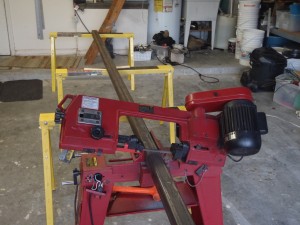 I purchased all of the steel needed, but cutting to exact lengths was going to add some significant expense to the project. With some borrowed industrial grade tools from local reefer friend Iggy, the steel is all cut to exact lengths and all that is left is some miscellaneous fabrication and trimming. The next step is getting it to over to Dave the welder, a guy that builds race cars, monster trucks and a lot of other neat stuff.
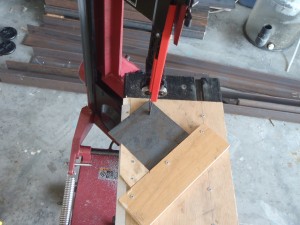 One of the challenges was to cut 32 5″ gussets. Gussets are triangular pieces of steel that are welded in the corners in order to reinforce the joints against lateral stresses. Using the bandsaw, a jig was made to hold the pieces at the correct angle to make the 45° cuts. There is a total of 346 lbs of steel.
Building the Tank
The sump work is started
Reef Savvy is working on the tank
New Tank Mock Up
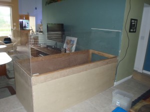
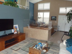
We needed a good visual to start getting used to what the new tank will look like. I built a mock up of plywood and acrylic so we can start getting used to the new monster in our living room.
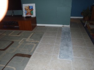
The area where the old tank came out is providing a challenge. I have a few spare floor tiles, but not enough to repair the area. Thinking ahead to a day when there would not be a tank here, it will just have to be replaced with another divider wall. The stand will have leveling feet, so the differences will be easy to deal with.
Demolition Day
The 18-year old 79 gallon fish tank had to come out, and some structure along with it. It didn’t take long, but the refinishing looked like a challenge. Especially the ceiling, it would be nearly impossible to match the texture after it was patched. Then I got this brilliant idea that a return air grill will cover the patch and look way better than a repair.
The Tank Location
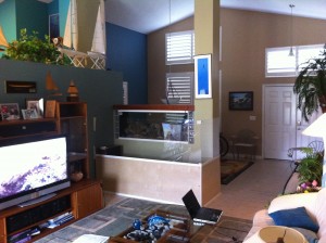
Pictured here is our 18 year old FOWLR (Fish Only With Live Rock) tank before demolition. You can see some plywood and acrylic attached to the back side of the column, a mock-up to help visualize the size of the planned tank.
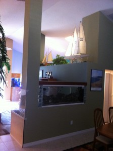
The column to the ceiling will be removed along with the wall section under the tank. The new tank will be located in the same area as the old one, but will be 7′ long (the distance from the column to the wall) and 3′ wide instead of the previous 12″. The new tank will be rimless with the lighting suspended from the ceiling with the lighting type yet undetermined.
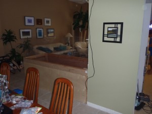
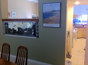 This view from the dining room shows the butler’s pantry on the opposite side of the wall from the tank. There will be an access panel that will allow maintanence to the Vortec MP-60 circulation pumps.
This is a view from the back of the living room. I have constructed a temporary mock- up of plywood and acrylic to get an idea what the new monster will look like.

